Comments by Dr. Cooper
ALL: Can you order your Figure names in sequential order within the document... not just for your section. Pur your own figure number and title and ignore the Atkins figure numbers and titles. Avoid using "we".
Islam (Blue),
Ideal Gas Isotherm
Figure 1 represents the Pressure-Volume relationship for the ideal gas at different temperatures.

Figure 1: Pressure-Volume relationship for the ideal gas at different temperatures
Each curve in the graph (hyperbola) shows the inverse relationship between volume (V) and pressure (p) at constant temperature (isotherm); as the volume of the ideal gas decrease, the pressure of the ideal gas increase and vise versa.
When applying enough pressure to gas it becomes liquid. When looking at Figure 1 above we see that the graph did not succeed in showing the point where gas becomes liquid. So, the ideal gas law is very good but not perfect and has its flaws.
Experimental CO2 Isotherm
Figure 2 represents the Pressure-Volume relationship for the real gas carbon dioxide at different temperatures.

Figure 2: Pressure-Volume relationship for CO2 at different temperatures
At high temperatures and low pressure, real gases behave similar to perfect gases.
When looking at Figure 2 above, we see that carbon dioxide is behaving like a perfect gas at 50°C and have the expected inverse relationship between volume and pressure. At lower temperatures, carbon dioxide does not behave like a perfect gas anymore.
The shaded area under the curve of 20°C, as seen in Figure 2, is liquid. As the volume is reduced at 20°C, few things are observed:
1) From the point A to C, carbon dioxide is behaving like a perfect gas.
2) At point C, the pressure does not increase when reducing the volume.
To assist in understanding what happened at point C, an experiment can be design to observe what happen to the pressure when the pressure is manually changed in a pressure gauge. What we will see is that as we decrease the volume, the pressure does not change and we will see the first drop of CO2 liquid. So at point C is where the first drop of water is formed and observed.
3) As decreasing the volume continues, point C is move to point D in a straight line with no change of the pressure level; more and more liquid is formed from the carbon dioxide gas. At this point, almost half of the gas is used to form the liquid.
4) At point E, all gas is used up and only liquid is present. If the liquid is compressed at this point, a high pressure will form. The reason behind this pressure formation is that liquid requires more pressure to reduce its volume than gas.
Also, when looking at the Figure 2, a special point is marked with a star at 31.04°C. This special point is called the Critical point. As the volume continue to decrease above this point, a mixture of liquid and gas is formed. The formed mixture is called Super Critical Fluid. Super critical fluid has a unique chemical properties; it can dissolve in liquid and can diffuse through gas. Below the Critical point is all liquid and above this point is super critical fluid. The critical temperature (Tc) for carbon dioxide is 31.04°C and it is different for every gas. From the citical point, the critical pressure and the critical volume can be obtained.
Lori Alexander - pink
Virial Equation of State
Two virial equations exist (figure 3 and 4) and can be used when calculating the pressure of real gases. These equations are much more accurate than the ideal gas equation because they take into account the volume and interactive forces of the molecules. As mentioned previously, under ideal conditions (low pressure and large volume) very minor interactions exists between molecules so the ideal gas equation is most appropriate. However, under non-ideal conditions (high pressure and small volume) the virial equations will provide more accurate data.

Figure 3: 1st virial equation of state

Figure 4: 2nd virial equation of state
Many virial coefficients exist -- the more coefficients provided experimentally, the more accurate the data. The second virial equation (figure 4) is more useful if experimental data for B and C are provided.
1 = 1st virial coefficient
B = 2nd virial coefficient
C = 3rd virial coefficient, and so on
Virial coefficients B, C, and others are dependent on the type and temperature of the gas. Therefore, the value of the virial coefficient changes with a change in temperature. Figure 2 above exhibits the experimentally determined graph of CO2 at various temperatures. Table 1 lists the second virial coefficient, B, at various temperatures for various gases. A table does not exist for the 3rd virial coefficient, C. Therefore if attempting to compute CO2 at 25°C, C will have to be provided experimentally.
Temperature
| |
273K |
600K |
| Ar |
-21.7 |
11.9 |
| CO2 |
-149.7 |
-12.4 |
| CO2 |
-10.5 |
21.7 |
| Xe |
-153.7 |
-19.6 |
Table 1: Second virial coefficients, B/( /mol)
/mol)
van der Waals equation
Another equation of state for real gases, which is less precise but easier to solve than the virial equation, is the van der Waals equation, figure 5 and 6. Figure 6 is a more convenient way to express the van der Waals equation.

Figure 5: van der Waals equation

Figure 6: van der Waals equation
The theory behind the van der Waals equation is the fact that real gases take up volume and molecular forces exists. Therefore, the van der Waals equation takes this fact into account by designating two van der Waals coefficients, a and b. Coefficient a takes into account the volume taken up by molecules, and coefficient b takes into account the reduction of pressure by molecular attractive forces. Table 2 lists the van der Waals coefficients for common gas molecules. The van der Waals coefficients are independent of temperature but gas specific.
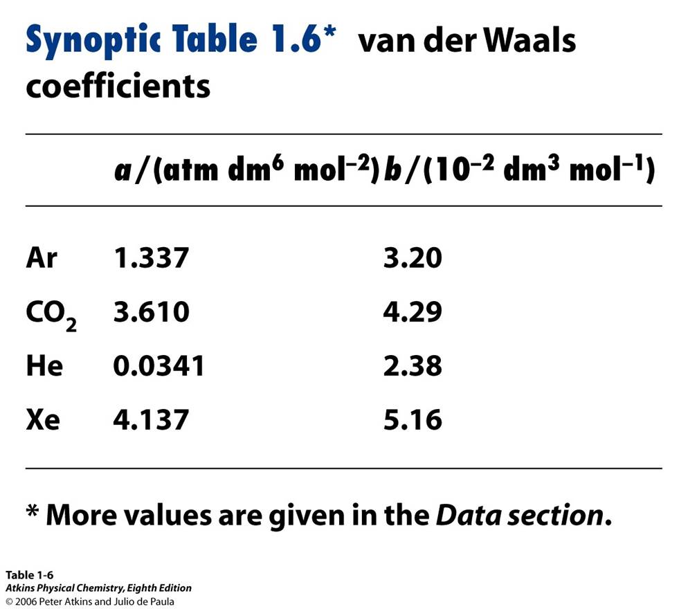
Table 2: van der Waals Coefficients
van der Waals equation reliability
To test the reliability of the van der Waals equation in predicting the action of real gases, a comparision of the isotherms found experimentally, figure 7, and the isotherms calculated using the van der Waals equations, figure 8, can be observed.

Figure 7: Experimental isotherms at different temperatures for CO2

Figure 8: Calculated isotherms using van der Waals equation
Experimentally, figure 7 exhibits real gas behavior of CO2with a critical temperature of 31.04°C with a critical isotherm observed at this same temperature. When comparing the isotherms of figure 7 and figure 8, the calculated values plotted using the van der Waals equation predict the same behavior as the experimental isotherms with an increase in pressure corresponding to a decrease in volume above the critical temperature, T/Tc = 1. However, below the critical temperature, the oscillations in figure 8 are inaccurate because they show an increase in pressure with an increase in volume, which is unrealistic. However, the Maxwell construction, figure 9, can be used to compensate for the inaccurate oscillations determined by the van der Waals equation below the critical temperature. A Maxwell construction is performed by replacing the horizontal line along the isotherm where the areas above and below the line are equal. This technique allows for approximation of actual data by reducing the volume without increasing the pressure.

Figure 9: Maxwell construction
Calculating critical constants using van der Waals equation
The critical constants of a real gas (Pc, Vc, Tc) can be calculated using the van der Waals equation because the 1st and 2nd derivatives are zero at the point of inflection, figure 10. To perform this calculation, the 1st and 2nd derivatives are set equal to zero and the sum of the two derivatives are solved using the van der Waals equation, figure 6. The calculation of the critical constants are another way to determine the van der Waals coefficients, a and b.
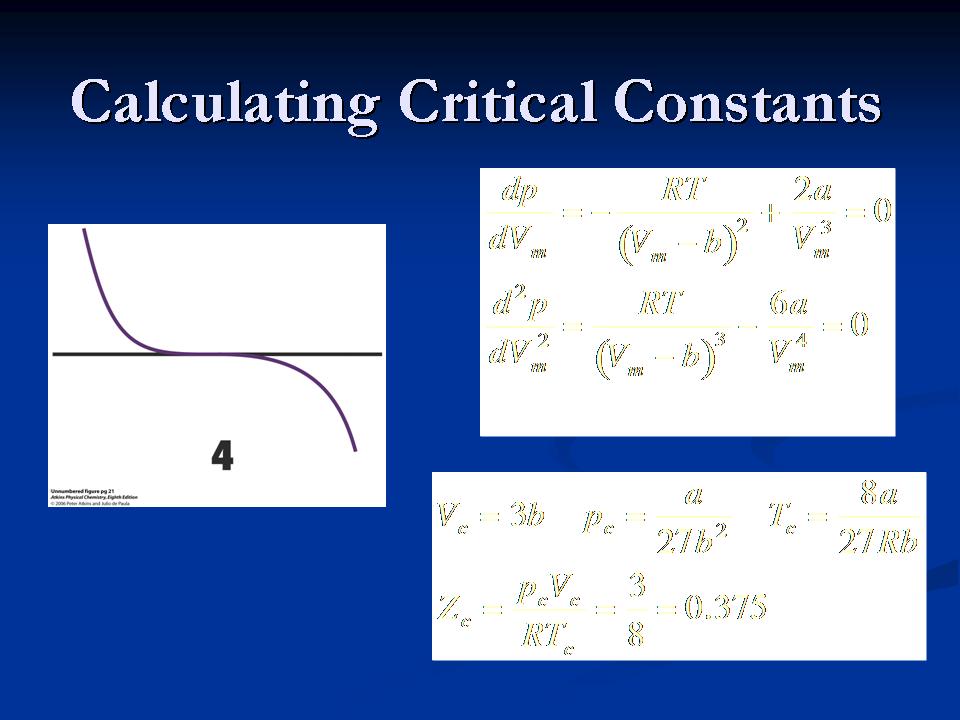
Figure 10: Horizontal line exhibits the zero point of inflection
To verify the value of the critical constants, the critical compression factor, Zc, can be calculated and its answer compared with the value in Table 3.


Table 3: Critical constants of gases
The flaw in the van der Waals equation is that the critical compressibility always calculates the same compressibility of a gas without taking into account the type of gas. Real gases have different compressibility. In summary, the van der Waals equation is not perfect especially below the critical temperature but it is a useful tool that produces some of the feature of real gas isotherms.
Sirin Akhter (purple)
The First Law
Thermodynamic is part of the physical chemistry that can be seen at macroscopic properties like temperature, pressure and volume. The basic knowledge of the system and surrounding is required in order to understand the full concept of thermodynamic. System is the miniature part of the universe that we are interested in, and surrounding is everything else in the universe. Surrounding also can be described as the place where observations can be made.

Fig.12 In this figure it shows that the solution in the beaker is the system and everything out side of the beaker is the surrounding.
Types of System
The boundary that separates the system and the surrounding developed the three types of system. A system can be open, which means heat, energy and matter can transfer through the boundary. A system can also be closed, where matter can not be transfer at all, however energy and heat can transferred. Isolated system is the third type of system, where neither energy nor matter can be transferred. The figure below shows the three types of system.

Fig 13. (a) Both matter and energy are transferable. (b) Only energy can be transfer. (c) Nothing can be transferred.
Walls and processes in the System
In addition to having different type of system, our system is also constructed physically with different kind of walls. A system can have a rigid wall that can not move; therefore no work will be done by that system. A system can also have a moveable wall which allows the system to do work. The system can also have either adiabatic or diathermic wall, which can classify if heat can be transferred or not through the boundary. Adiabatic wall allows no heat transfer and diathermic wall allows heat transfer. Another kind of wall a system can have is the permeable and non- permeable wall. With the permeable wall gas molecules can exchange and with the non-permeable wall gas molecules can not exchange with the surrounding.
An adiabatic process is where no heat is being exchange between the system and surrounding. Referring back to fig.13 adiabatic process is same as (c) isolated system. Another process is called the isothermal process, in which the initial and the final temperature are equal. Another word, since our surrounding is so big compare to our system, even if the system is heated and let it come to back to the equilibrium, it is always going to be the same temperature that started out at the beginning. This introduces the concept of equilibrium.
There are three kindof equilibrium; thermal, mechanical and chemical equilibrium. In thermal equilibrium the temperature in the system and surrounding are the same at beginning and at the end. In mechanical equilibrium the pressure in the system and surrounding are the same and chemical equilibrium the chemical concentration is the same.
Heat, Energy and Temperature
Heat and temperature are two different aspects. Heat is form of energy that being transferred across a temperature difference. Temperature is the hotness of an object.
An endothermic process is when the energy is attained from heat. An exothermic process is when energy is release as heat, however since heat is process, based on the definition of heat, what kind of containers are going to be used must be taken into consideration. If an endothermic process occur in a diathermic container will result in heat being transferred from the surrounding. Therefore the container will be cold, and the surrounding will transfer heat to container so it can come back to the thermal equilibrium. If an endothermic process occurs in an adiabatic container, then energy will not be transfer, as result the container will get cooler. Therefore the temperature of the container will be lower than the surrounding and it can not go back to the thermal equilibrium.
If an exothermic process occurs in diathermic container the heat is going to be transfer from the system to the surrounding. An exothermic process in an adiabatic container will heat up the container.

Fig 14: (a) This is an endothermic process where heat is being transfered from the surrounding to the system in an adiabatic system where the temperature is decreasing. (b) This is an exothermic process where heat is transfered from the system to the surrounding in a adiabatic system where the temperature is increasing . (c) Here an endothermic process in a diathermic container, energy is being transfered as heat from the surrounding and the temperature in the system stays constant in both c and d. (d) An exothermic process, or isothermal process where heat is transfered from the system to the surrounding.
Comments (5)
lalexan2@gmu.edu said
at 1:23 am on Sep 14, 2009
I am having problems downloading my pictures and equations. Hopefully, I will be finished by tomorrow afternoon. Lori Alexander
ialhaj@gmu.edu said
at 2:10 pm on Sep 15, 2009
Hay Guys what happened. My section (1) is all mest up...:(
lalexan2@gmu.edu said
at 5:45 pm on Sep 15, 2009
Hi, I think I fixed it. Read it over and let me know if you are missing something. Lori
Sirin Akhter said
at 11:39 pm on Sep 15, 2009
thank you it looks good.
ialhaj@gmu.edu said
at 12:29 pm on Sep 16, 2009
It looks good, Thank you and good job on your section :)
You don't have permission to comment on this page.